

The project began at the beginning of September. We started by deciding which motors we would use and the necessary gear ratios for each mechanism. Once we decided that, we made rough sketches of the gear and motor layouts for the rollers and the pivot mechanism.
While designing the intake, the geometry of the intake up and down positions constantly made it challenging for us to design a good mechanism. We had to change parts of the master sketch very often, and it is important to know which parts you should and shouldn’t change. For example, changing the pivot points of the intake or the height of the stowed position would be fine, since the intake would work mostly the same. However, changing the down position might prevent the intake from effectively intaking since its position relative to the ball could be incorrect. Also, changing the horizontal position of the up position might make the robot reach over its frame perimeter.


We decided to try stub rollers on this intake. Initially, we decided that the stub rollers would be mounted by putting them against the joint of the polycarb plates.
However, we realized that the little surface area of contact between the stub roller and the arm could make the rollers unstable, so instead we made the stub roller go through the arm joint.
Make sure you account for the width of the stub rollers when deciding where the up position is, since if the stub roller has a bigger diameter than the roller, then the master sketch needs to show that to make sure the robot fits in the frame perimeter. If you look at the circle that has another construction circle around it, the construction one represents the stub, while the solid one represents the roller. Neither should reach over the frame perimeter.


One problem we kept running into was component packaging. For example, on the side of the intake with the motor that controls the pivoting, there is a hex shaft that runs in between a chain. Although it is not a problem itself, it highlighted the limitations of how the gearbox would need to be packaged. Additionally, since the chain goes above the swerve module, it cannot be significantly lowered. One concern we could not address was that the jackshaft was too high.

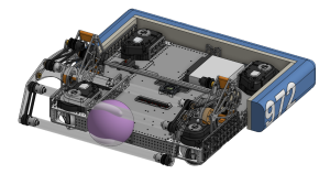
It looks like the ball we intake may struggle to get over the hex shaft since the hex shaft is too high up. However, we cannot really move the hexshaft lower, or the chain would interfere with the swerve module. Consequently, we had to solve this issue when designing the indexer polycarb.
On the other side, originally, the motor for the rollers was between a chain, which made it really close to interfering. However, we decided to lower that motor for a lower center of gravity, which solved that problem, but then we ran into another one.

The light grey holes are where the motor mounts, and the dark grey is the waffle. The motor mounting holes are awkwardly placed around the waffles. Finding a good motor position that has space for mounting holes can be difficult, and the best solution is to sketch all the motor holes at the same time and move them around in the sketch until you find a good spot. Another problem was that when we moved the motor down, we added a belt to it to allow it to spin the rollers, meaning the center-to-center distance from the motor to the next pulley could only be a few discrete values.
For the CAD assembly, most of it is pretty self-explanatory; you can just spam cylindrical or revolute mates, since that’s pretty much how 4 bars work in real life. To make it stop at the hard stops, measure an angle in the master sketch and put it as the limit in the corresponding mate.

Once everything had been machined, we moved to assembly. We started by assembling each of the gearboxes separately. At the onset of that process, we made the unfortunate discovery that not only were we missing 3D printed spacers, but the spacers we did have were incorrectly toleranced, impossible to move laterally along the hex shafts, and even breaking in some places. Going forward, we learned that we had to redo our tolerancing on 3D prints, specifically those on the hex shaft. Once we assembled the gearboxes with a mix of redone 3D print spacers and approximated the rest using multiples of 1/16th spacers, we moved to combining the gearboxes with the center shaft, adding the chain, and assembling the polycarbonate 4-bar mechanism.
While assembling the 4-bar mechanism, we realized we had ordered the wrong bushings to allow for the rotation of each arm. This held up assembly for a few days until we could obtain the correct bushings for the holes we machined. Upon receiving them, we made the additional unfortunate discovery that we had the wrong metallic spacers used for rotation in the bushing. Instead of ordering new ones, which we knew would take days, we laythed down a hex shaft to meet our specific criteria and used that as a fix, working just as well, if not better, than the actual purchasable spacers.
Moving on to adding the chain, cutting the chain to the necessary length, and adding the chain tensioners proceeded without any major issues, yet once the chain was fully assembled on both sides, we realized that the chain had been clocked incorrectly. We initially hypothesized that the chain had been sized one link off, yet re-doing the chain revealed that that wasn’t the case. Instead, because we used a 38t sprocket on a ring of 6 holes, the sprockets on either side had been asymmetrically assembled when making the gearbox, requiring a lengthy disassembly and reassembly to get the sprockets symmetrical and the chain reset.

In completing the assembly of the intake project, we learned a lot of important things about not just intake assembly, but general assembly as well. We obtained a new basis for 3D print tolerancing, placed a greater emphasis on ordering the right parts for each project, and learned to focus on ensuring the assembly mirrored the CAD to avoid time-consuming mistakes.
If you are interested in taking a closer look at our Infinite Recharge Intake, we are planning to publish our CAD ahead of the Rebuilt Kick-off.